
Hardware Hacking Fundamentals: Finding the Debug Interface
Updated August 5, 2026 · Written by PWNMI — see About.
Everything else on this site assumes the target is reachable over a network. Hardware hacking is what's on the other side of that assumption: you have the physical device in your hands — a router, an IoT gadget, a badge reader, a car's infotainment unit — and the attack surface is the board itself, not a listening port. It's a genuinely different skill set from network or web testing, but it leans on a lot of the same instincts: find the interface nobody meant to leave exposed, see what it gives you, and check whether what you find would matter on a real engagement.
The legal line, stated first
Physical possession changes the ethics math in a way network testing doesn't. Buying a used router specifically to take apart is fine — it's yours. Popping the back off your employer's badge reader, or a device on a client site, without explicit written authorization is not a gray area; it's the same unauthorized-access problem as scanning a network you don't own, just with a screwdriver involved. Everything below assumes hardware you own outright or are contractually authorized to test.
Finding the debug interface
Most embedded devices leave one of two things exposed on the PCB, usually not on purpose:
- UART — a 3-4 pin header (TX, RX, GND, sometimes VCC) wired to a serial console, often left connected for the manufacturer's own debugging and never disabled before the device shipped.
- JTAG or SWD — a hardware debug interface built into the CPU itself, giving far more access than UART (memory read/write, breakpoints, sometimes a way around secure boot entirely).
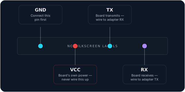
Production boards almost never label these. The realistic workflow is: find the main SoC's part number printed on the chip, look up its datasheet, and use a multimeter in continuity mode to trace candidate pins against what the datasheet says should be there. Unpopulated through-holes near the main processor are the most common shape a debug header takes — treat "no header, no silkscreen" as the default case, not an exception.
UART: usually the fastest way in
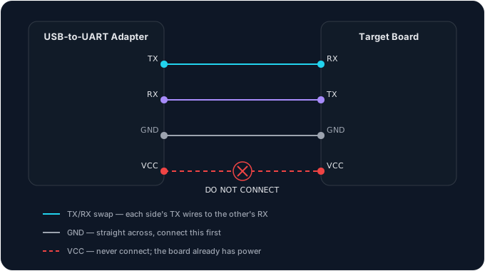
Once you've identified TX, RX, and GND, a USB-to-UART adapter and a terminal program (screen, minicom) is often all it takes to land on a boot log or a live shell — sometimes even a bootloader prompt you can interrupt.
A few things that matter more than they look like they should:
- Never wire up VCC. The board is almost always already powered by its own supply. Backfeeding power from your adapter is one of the more common ways to damage a board that would otherwise have been fine.
- Match logic levels. Most modern gear runs UART at 3.3V, not 5V — connecting a 5V adapter to 3.3V logic can damage the transceiver on either end. Check before you clip on.
- Baud rate is a guess until it isn't. 115200 and 9600 cover a lot of devices, but a logic analyzer with a UART protocol decoder will read it off the wire directly instead of you cycling through common values by hand.
JTAG/SWD: full debug access, if you can find the pins
JTAG and SWD sit a level deeper than UART — this is the interface actual chip debugging tools use, and on a device where it's still enabled, it can mean reading out flash contents directly or bypassing checks that would otherwise stop you from running modified firmware. OpenOCD is the open-source tool most cheap JTAG/SWD adapters (ST-Link clones, J-Link clones) work through. When the pins genuinely aren't labeled and continuity tracing against the datasheet isn't getting anywhere, tools like JTAGulator exist specifically to brute-force an unknown header and identify which pins are which.
This is a deeper rabbit hole than UART and worth treating as a second step once the basics are comfortable, not a starting point.
Firmware extraction and analysis
There are two ways to get firmware off a device, and the second one is where most beginners should actually start:
- Pull it off the board — chip-off (desoldering the flash chip and reading it in a programmer) or an in-circuit read over the same SPI/JTAG pins discussed above. This requires the soldering and debugging skills covered so far.
- Download it — a huge number of consumer devices publish firmware update files directly from the vendor's support site. No hardware access required at all, and it's the same binary that would end up on the board either way.
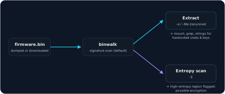
Either way, you end up with a .bin file, and that's where binwalk comes in — it identifies embedded filesystems and compressed sections inside the blob and extracts them, at which point ordinary Linux tools take over: mount the extracted filesystem, grep for hardcoded credentials or API keys, read init scripts to see what actually starts on boot. Entropy analysis (also part of binwalk) flags sections that don't compress or extract cleanly — often the tell for an encrypted region worth a closer look.
What you're actually looking for
The vulnerability classes that show up over and over in real hardware and firmware:
- Hardcoded credentials or API keys baked into the firmware image
- Debug interfaces (UART, JTAG, sometimes an undocumented shell command) left enabled in a production build
- Missing or incomplete secure boot — no signature check on what the device is allowed to run, meaning modified firmware just... runs
- Update mechanisms that accept unsigned firmware, or verify it insecurely
- Config files or logs with credentials or tokens stored in cleartext
None of this requires exotic tooling to find. A surprising amount of it turns up from binwalk -e and then grep -r through the result.
RF: hardware hacking over radio instead of copper
Sub-GHz replay attacks (garage doors, key fobs) and RFID/NFC badge cloning are hardware hacking too — the debug interface metaphor doesn't quite apply, but the "physical device, physical access, explicit authorization required" rules do. The Flipper Zero toolkit page covers this side in more depth; it's a natural next device once UART and firmware work feel comfortable.
Building a practice bench
A USB-to-UART adapter and a logic analyzer cover the large majority of what's in this guide, and both are inexpensive. A decommissioned router, a broken smart-home gadget, or anything similar pulled from an e-waste pile or your own closet is a genuine practice target — no lab environment needed, no CVE required, just a board and the willingness to open it up. Once single-protocol adapters start feeling limiting, a Bus Pirate covers UART, SPI, I2C, and 1-Wire from one device instead of swapping tools per protocol.
Common mistakes
- Connecting VCC or mismatching voltage on a UART header — the single most common way to damage a board that would otherwise have been completely fine to work with.
- Assuming an unlabeled board means no debug interface exists. Silkscreen labels are the exception on production hardware, not the rule — the multimeter-and-datasheet approach is the default workflow, not a fallback.
- Soldering first, downloading the vendor firmware second. If the update file is publicly available, get it and run it through binwalk before ever touching an iron — it's the same firmware, with none of the risk.
- Testing hardware without a clear ownership or authorization trail. The legal line at the top of this guide isn't a formality — it's the difference between a hobby and a real problem.
Next step
Binwalk is worth being genuinely comfortable with before doing much else here — most of what a beginner finds in this space comes from firmware analysis, not soldering. For the command-line habits that carry over once you're inside a shell over UART, see Linux Fundamentals.
Get new write-ups in your inbox
New roadmaps, tool walkthroughs, and lab write-ups. No spam. Unsubscribe anytime.